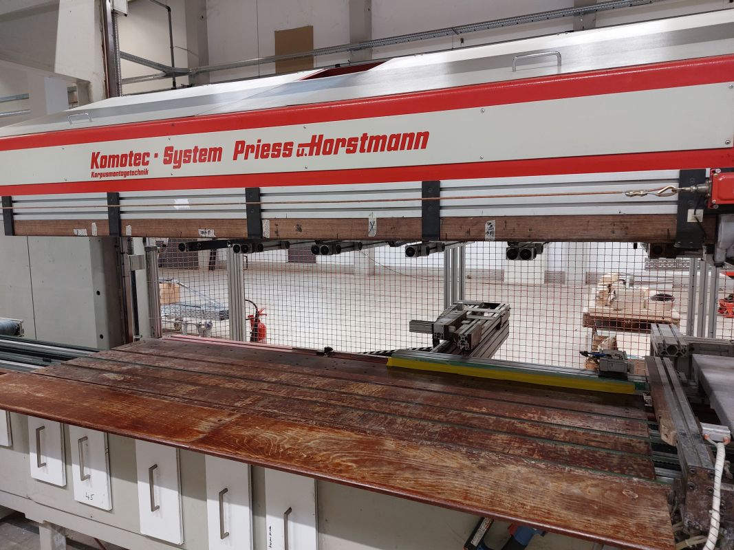
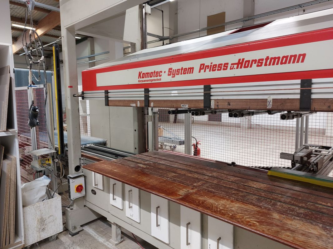
BrandPRIESS U. HORSTMANN
typeBMA-DLS-CNC
stateUsed
stock number0401716
year2000
Workpiece dimensions
Length: 250 - 2500 mm
Width: 130 - 700 mm
Thickness: 16 - 19 mm
Questions about this machine
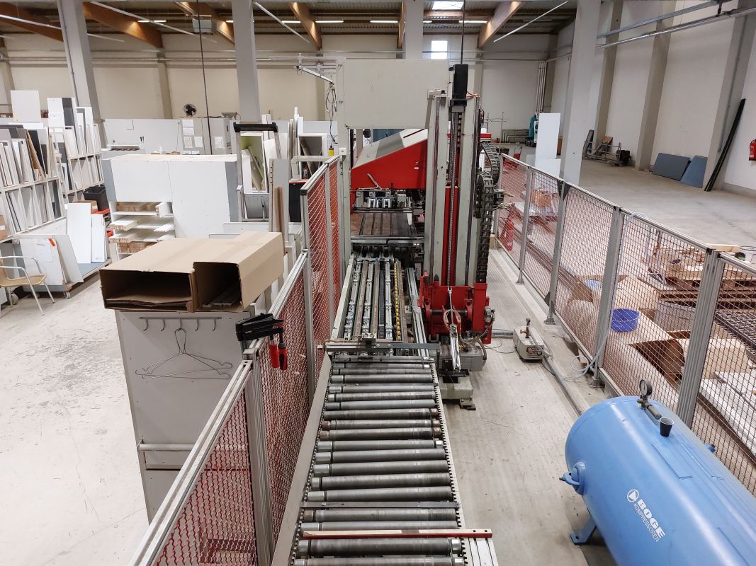
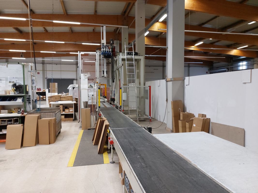
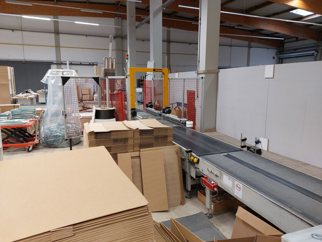
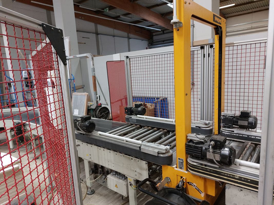
drilling and assembly line
Brand: Priess u. Horstmann
type: BMA-DLS-CNC
not rebuilt- without warranty
Year of construction: 2000
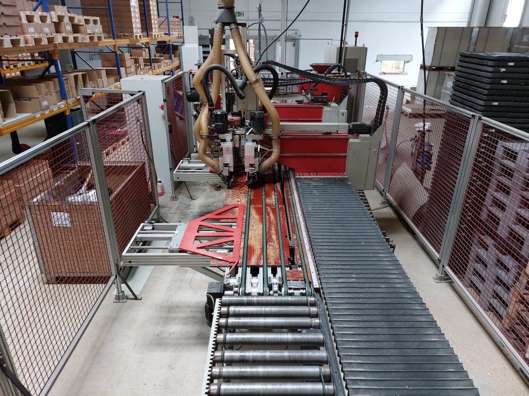
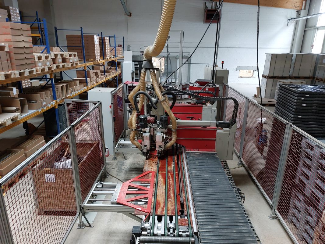
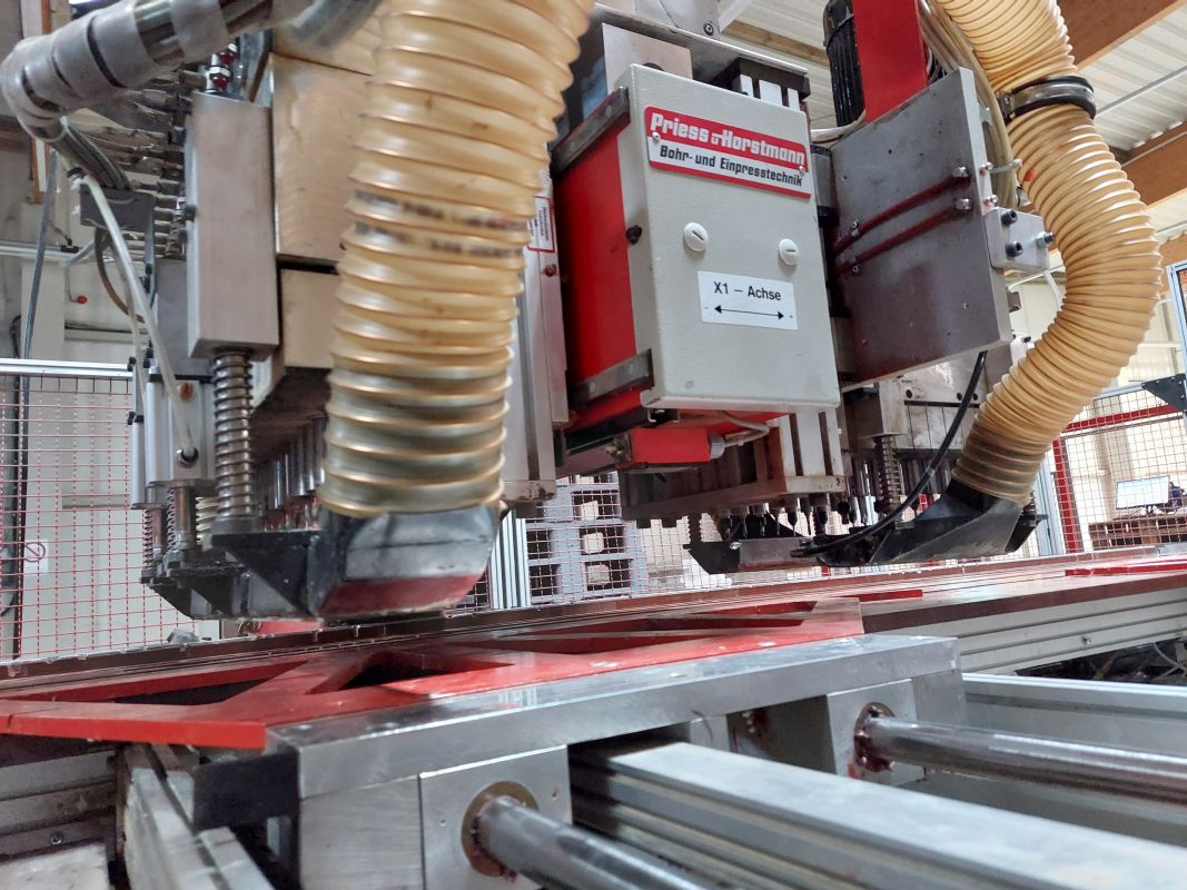
BMA-DLS-CNC drilling and assembly system
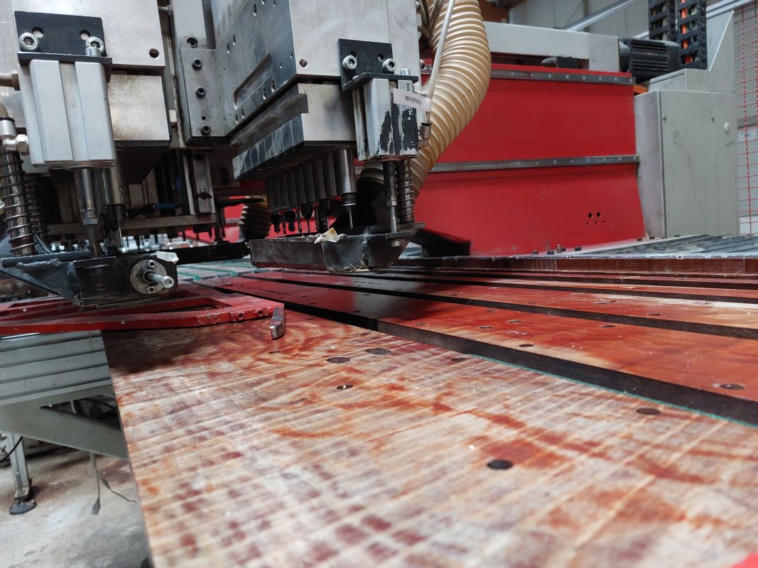
for the commission-based production of sides. Drilling for construction holes, running rails, shelf supports, connecting fittings, mounting plates, etc. The fittings can also be pressed in automatically. Feeding via magazine or vibratory conveyor (see below).
The basic machine consists of a solid, torsion-resistant frame with precision guides to accommodate the units. Control cabinet for the machine control (electro-pneumatic control) can be installed separately (see A-plan).
Electrical connection:
400V +/- 10%, 50 Hz (3 phases with loadable neutral conductor), approx.18 KW. In accordance with VDE0100-T482, the system must be protected on site by an RCD. on site.
Service unit:
R 1/2” with pressure switch and air accumulator, operating pressure 6-7 bar. Supply line min. 1” (arrangement see A-plan) Extraction: min. 32 m/sec air speed at the respective nozzles of the units (required negative pressure 2200 Pa., capacity 40m3/min).
Paint finish:
Machine and control cabinet pebble gray (AAL 7032)
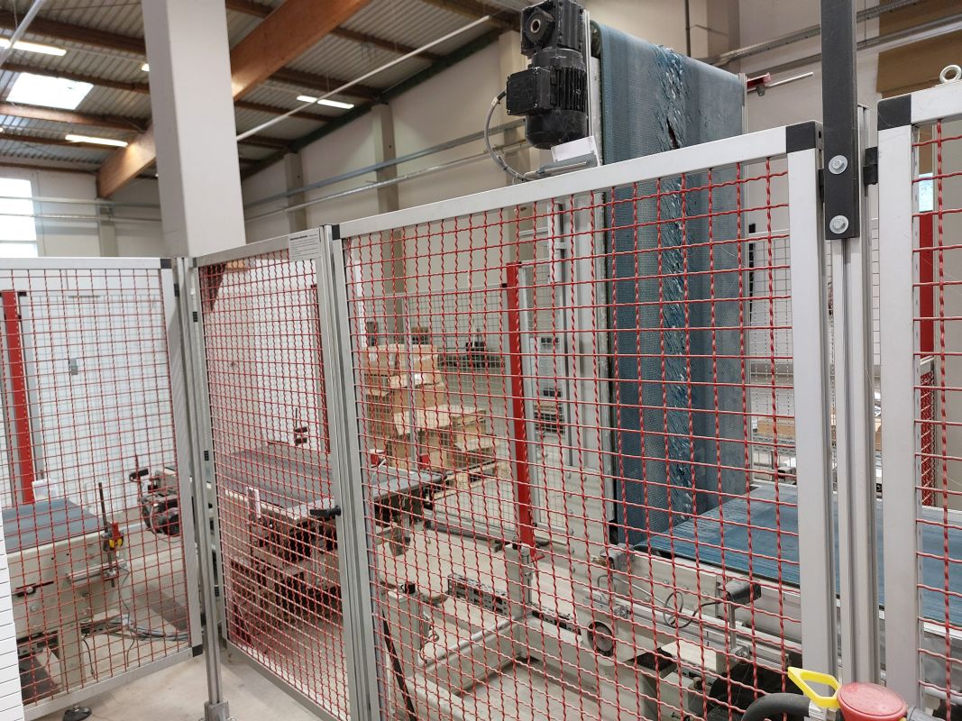
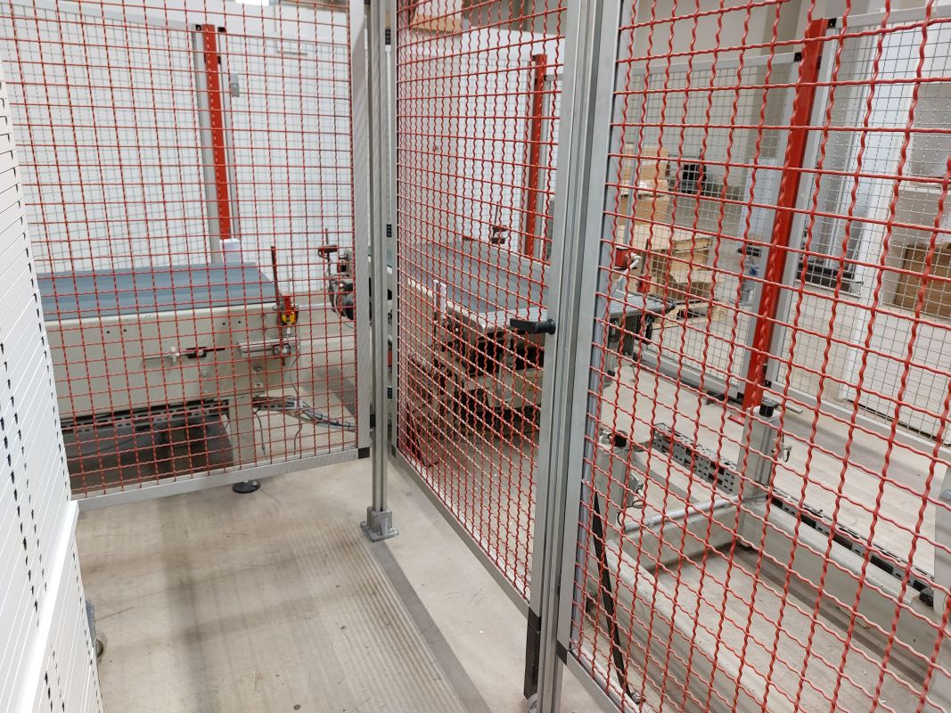
Supports and protective grille fire red (AAL 3000)
Motors and extraction hoods matt black (RAL 9005)
Workpiece dimensions:
- Length: 2x250 mm 2x1100 mm/1x2500 mm
- Width: 130 mm 700 mm
- Thickness: 16 mm 19 mm
The ratio of part width to part length should not exceed 1:1. Parts that are narrower than 200 mm only run on one conveyor belt and must therefore be monitored during transportation, as perfect transportation is not always guaranteed. Shelves for beveled cabinets are manually inserted directly into the machine, A second longitudinal stop is installed for these parts at width 300. For the beveled the rear edge of the beveled shelves is placed against the stop, the transverse aligner remains at the maximum opening dimension. The smallest shelf width (X dimension) is 268 mm. The smallest carcase height is 298 mm.
Working height: 930+/-20 mm
Cycle times:
Entry and exit with alignment: approx. 6 sec.
per drilling cycle and approx. 200 mm travel approx. 2 sec.
approx. 3 sec. per press-fit cycle.
Servo positioning system:
Target and actual value output and display for the axes by the CNC control system. Positioning via ball screws with backlash-free nut and highly dynamic, digital three-phase servomotors with clocked 4-quadrant controllers. Travel speed: approx. 60 m/min (X-axis), approx. 50 m/min (Y-axis).
CNC screen control:
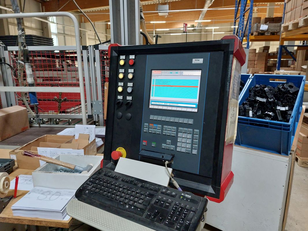
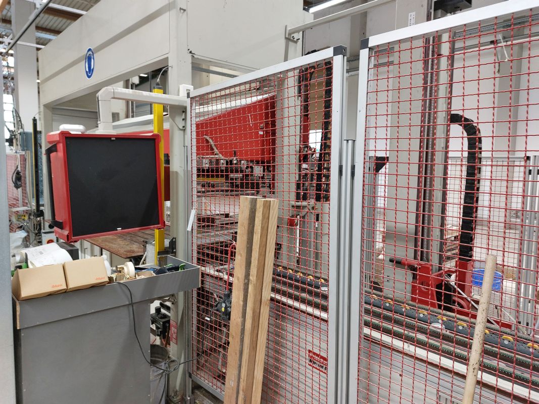
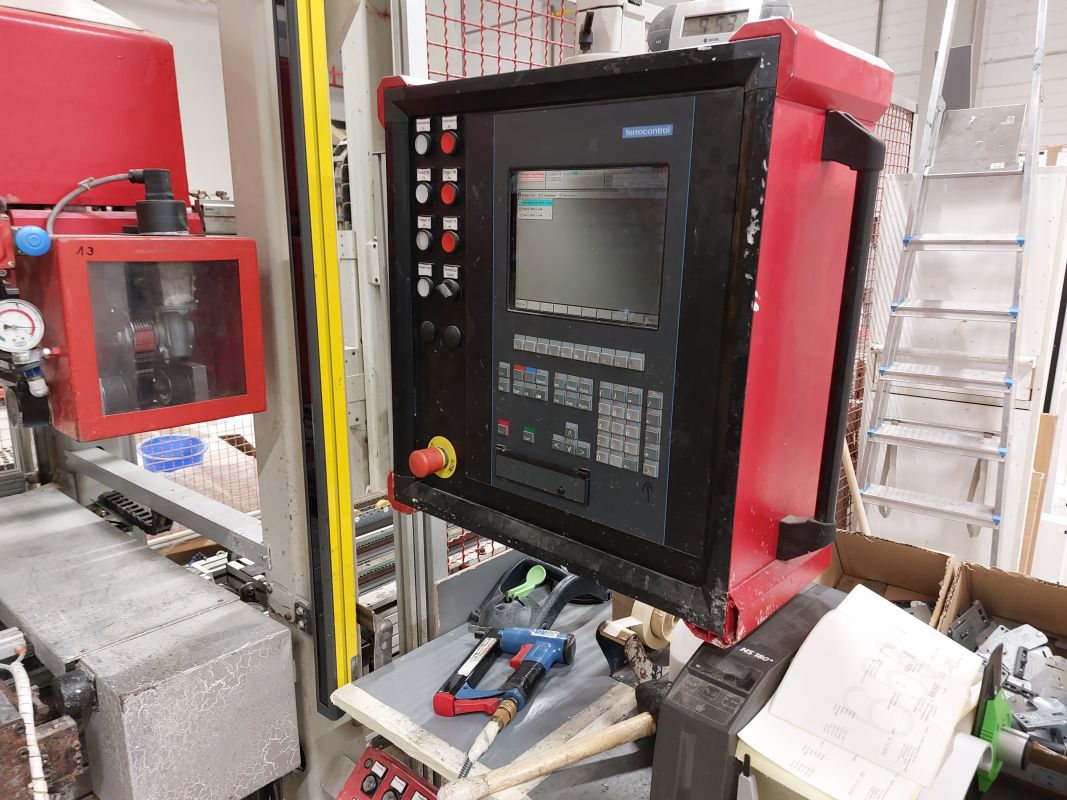
Convenient CNC screen control with TFT color monitor and dust-proof membrane keyboard, installed in a stand (see A-plan). Ferrocontrol control Industrial PC (FIPC). Practice-oriented and proven operating software with on-screen operator guidance for all input and control functions, with function keys whose meanings are explained in plain text on the screen. The workpieces are called up for production via a multi-digit drill code, which can be extended by variant programming, additional parameters, part dimensions stop and number of pieces. The stacking location data is passed on to to the upstream loader.
Program memory for the current main program and for 250 sub-programs. External PC (to be provided by the customer) as storage and programming location for the drilling data. Integrated, freely programmable control (FPS) to achieve optimum processes and maximum operating to achieve optimum processes and maximum operational reliability. Fault diagnosis via LEDs and plain text displays on the screen, special service routines for simple troubleshooting.
Machine equipment (B):
1.) 1 screen control unit with its own housing and separate control panel to be machine, including plug connector to the control cabinet, instead of Screen built into the control cabinet
2.) 1 interface for connecting the master computer (PC with WIN NT), incl. cable and their routing within the system (not in on-site cable ducts or similar).
3.) 1 serial interface (RS 232) for connecting a modem for remote maintenance. The modem is included in the scope of delivery; the customer must provide a TAE connection socket (direct dialing capability) on each machine PC. The modem can be taken over after the warranty period has expired (subject to a charge) be taken over.
4.) 1 Programming software, for IBM or compatible PCs (operating system WIN NT). Recommended configuration: Pentium with min. 32 MB main memory, hard disk 500 MB (access time<=18ms), serial interface (RS 232), floppy disk drive 3.5(1.44 MB), SVGA color screen (1024*768). The software is provided in advance on a 3.5” floppy disk during the programming training, Duplication is only permitted for internal use.
5.) 1 Special software for the master computer, for creating and editing article and work lists, structure similar to the description “Sanipa W07- 1385.DOC”, which is available to you. Special software on the machine control unit for transfer of the work list from the master computer.
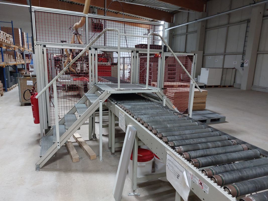
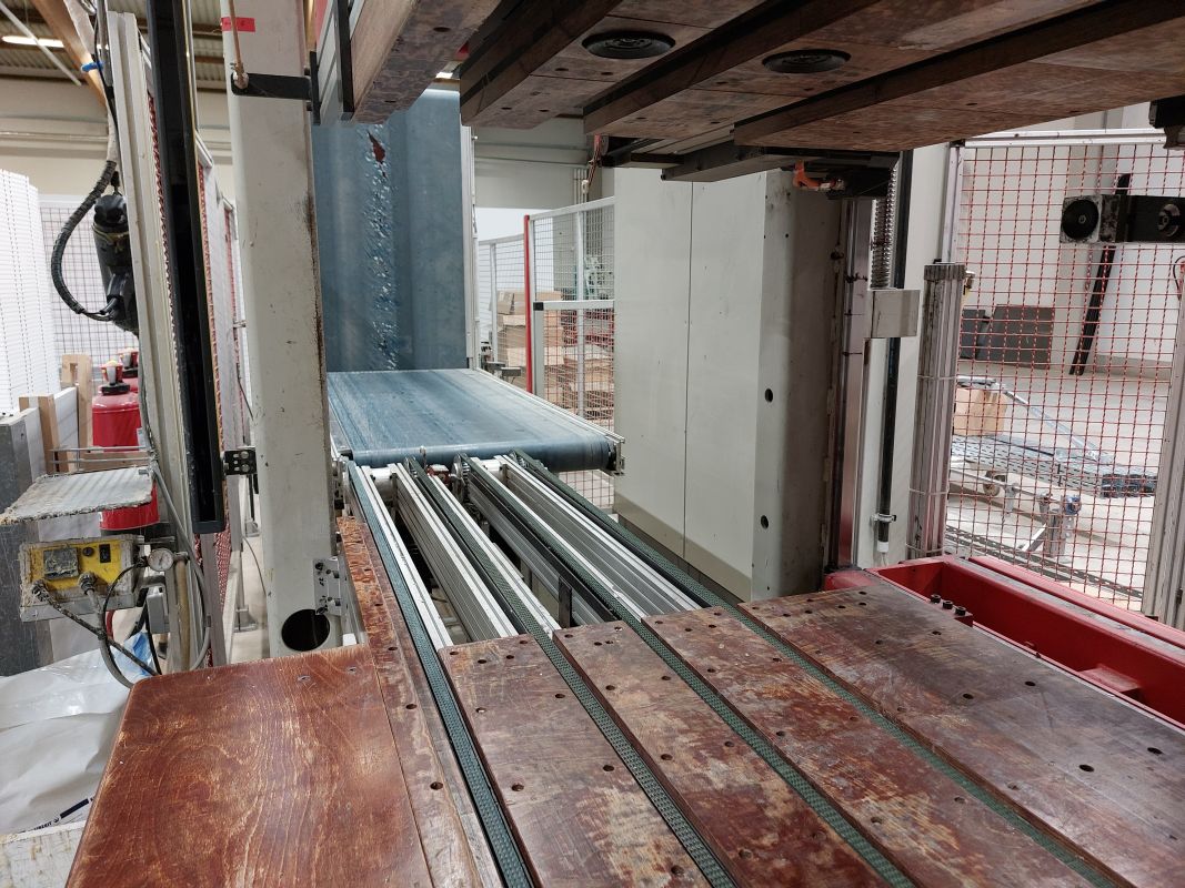
6.) 1 automatic workpiece infeed and outfeed in longitudinal direction (from left to right) via right) via 4 lowerable toothed belts, speed adjustable via frequency converter adjustable from 50-100 m/min. Transport divided for two stations.
7.) 1 automatic alignment system in longitudinal (X3) and transverse direction (Y3+Y4) for left and right sides simultaneously. The reference edge is the front edge from the bottom or top. For short sides (up to approx. 1100 mm), the sides are fed in in pairs, long sides one after the other. The part length and width are automatically measured during clamping without any loss of time. This certain programmable cycles can be adapted to the actual workpiece sizes (compensation of tolerances).
Portal equipment 1:
8.) 1 drilling gantry, movable in the X-axis via a servo positioning system (X1), with precision guides for holding and adjusting the units in the Y-axis direction.
9.) 1 servo positioning system for the Y-axis (Y1-axis).
10.) 1 cross slide with precision guides for holding and adjusting the units in the Z direction with a servo positioning system (11-axis).
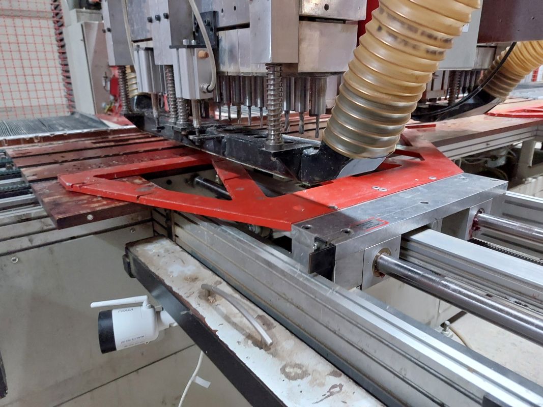
11.) 1 gearbox with 18 individually controllable spindles (n=6000 rpm). Direct drill holder, shank diameter 10mm. Arrangement of the gearbox in Y- direction for construction bores, rails, etc. Drive motor P= 2.2 kW (unit 1, spindle 11...28). 2 suction nozzles D= 80
12.) 2 gearboxes, each with 9 individually controllable spindles (n=7500 rpm). Direct drill holder, shank diameter 10mm. Arrangement of the gearbox in X-direction for row of holes, flap holder, etc. Drive motor P= 1.6 kW (unit 5, spindle 51...59). 1 suction nozzle 0=80
13.) 1 Adjustment of the two hole row units in relation to each other to 4 positions:
- Pos.1: A= mm (distance hole row hanger T330)
- Pos.2: A= mm (distance hole row US T45)
- Pos.3: mm (distance hole row US T55)
- Pos.4: A= 348 mm (distance base foot US T55)
14.) 1 suction collector for 4 suction hoses D=80 from the individual units and a central connection piece D=160mm. 1 potential-free contact for control of a shut-off damper in the on-site extraction system
Equipment gantry 2:
15.) 1 assembly gantry, movable in the X-axis via a servo positioning system (X2), with precision guides for holding and adjusting the units in the Y direction.
16.) 1 servo positioning system for the Y-axis (Y2).
17) 1 setting unit for mounting plates with journals positioned one behind the other, feed via a traveling magazine.
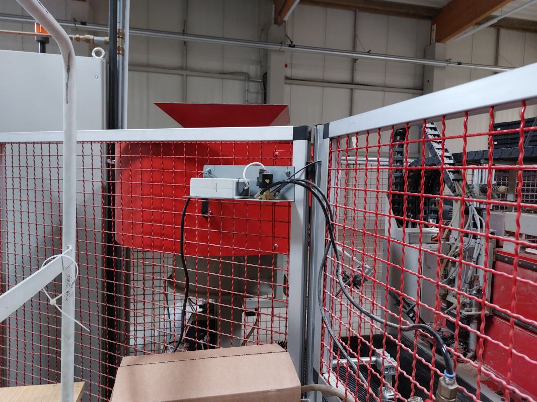
18.) 1 vibratory conveyor for mounting plates with feed magazine and automatic automatic refilling device for the traveling magazine. Vibratory conveyor with sound-insulating hood and hopper with pneumatic flap. The hopper is pulled out of the protective grille so that the mounting plates can be refilled from the front can be refilled by the operator. The vibratory conveyor is located on the right behind the outfeed conveyor.
19.) 1 glue bar on the support on the right, with material pressure regulator and 7 glue valves. Glue valves arranged in a grid (32 mm) (see UP1456 sheet), movable with the servo positioning systems (X2 and Y2).
20.) 1 glue specification for high-viscosity special glue (e.g. JOWACOLL 11480) in 30 I containers. Glue pump (ratio 10:1) with follower plate, filter and stopcocks. Set up behind the system in front of the protective grid.
21) 2 press-in units for base feet (rectangular design with 4 dowel pins BA6 4 / 6 4). The fittings can be rotated 180° in the press-fit unit. the press-in unit. Fittings are fed via 2 fixed magazines on the right behind the infeed conveyor. behind the infeed conveyor. Adjustment of the two units in relation to each other to 2 positions (348 and 248 mm) for shelf depths 55 and 45.
22.) 1 space preparation to accommodate 2 press-in units for shelf supports, incl. extension of the adjustment to 4 positions analogous to the perforated row drilling units.
23.) 1 grooving unit for rear wall grooves (2.2KW, approx. 7500 rpm) with toothed belt transmission. Tool dimensions: D=125, d=30, B=4.5 mm. Suction hood with connection piece D=100, potential-free contact for controlling an on-site shut-off damper.
24.) 1 drilling unit for center post drilling for floors (width >600), installed at the bottom of the machine table. machine table. After drilling and pressing in the base feet, the floor is the base feet is pushed into position by the longitudinal aligner X3 (2 drill holes D=8mm, T=12 at a distance of 16mm in the X direction).
Further equipment
25.) 1 infeed roller conveyor with round belt drive (under the portal loading), with three-phase geared motor and frequency converter v=60m/min at 50 Hz. Construction height 930+/-20 mm, usable width 700mm, rollers covered with plastic hose, roller pitch 100mm, length approx. 3,000mm
26.) 1 additional infeed roller conveyor with round belt drive, with three-phase geared motor and frequency converter v=60m/min at 50 Hz. Overall height 930+/-20 mm, usable width 700mm, rollers covered with plastic tube, roller pitch 100mm, length approx. 2,800mm. A scraper is fitted above the roller conveyor, which removes any support blocks (stacks of equalizing parts) from the side into a box. side into a box behind the roller conveyor.
27) Control of the subsequent assembly belts No. 1457
Manual workstation and feed belts:
3.1) 1 driven toothed belt conveyor as outfeed belt. Drive with three-phase motor and frequency converter v=60 m/min at 50 Hz (control range approx. 40 - 100 m/min). Overall height 930 mm, effective width 700 mm, length approx. 2,800 mm. Controlled by BMA no. 1456.
3.2) 1 belt conveyor as manual workstation with steel plate as belt support. Drive with three-phase motor and frequency converter v= 60m/min at 50 Hz. Overall height 930mm, belt width 700 mm, length approx. 2,800 mm. Including fold-up rollers on the outlet side in the area of the fire door, interlocking with the fire door control. 2 alignment rulers, pneumatically controlled, to push the workpieces forwards to a stop edge (changing the reference edge from the front edge to the rear edge). Controlled by the BMA no. 1456
3.3) 1 driven toothed belt conveyor as intermediate transport. Drive with three phase motor and frequency converter v=60 m/min (50Hz). Overall height 930 mm, effective width 700 mm, length approx. 2,800 mm each. Controlled by BMA no. 1456
3.4) 1 driven toothed belt conveyor as intermediate transport. Drive with three phase motor and frequency converter v=60 m/min (50Hz). Overall height 930 mm, effective width 700 mm, length approx. 2,800 mm each. Controlled by KP no. 1459
3.5) 1 roller conveyor with round belt drive as intermediate transport, with three-phase geared motor and frequency converter v=60m/min at 50 Hz. Overall height 930+/-20 mm, Useful width 700 mm, rollers covered with plastic hose, roller pitch 100 mm, length approx. 2,800 mm. A pneumatically liftable rake is attached to the roller conveyor, with which the first This rake lifts the bottom of the lower cupboard that enters first so that the right-hand side can overtake the bottom and enter the turner. The floor is then placed back onto the roller conveyor and transported into the outfeed area of the carcass press. The left side then finally runs into the infeed area of the carcass press. The base is manually removed from the press and inserted into the holding arms. Controlled by the KP no. 1459.
Feeding and turning device ZWA-2-CNC
The first incoming side is turned around the transverse axis and lifted, the second side runs through into the carcass press. No additional handling is required for the sides. The machine consists of a solid, torsion-resistant frame with precision guides to accommodate the lifting table.
Electrical connection: via the carcass press
Compressed air connection: via the carcass press
Paint finish:
Machine and control cabinet pebble gray (RAL 7032)
Protective grille and supports fire red (RAL 3000)
Motors matt black (RAL 9005)
Electrical, pneumatic and other purchased elements according to P+H standard
Workpiece dimensions:
- Enclosure height: 300 mm 2500 mm
- Enclosure width: 300 mm 1200 mm (250 mm only possible with allowance)
- Cabinet depth: 250 mm 700 mm
Working height: 930 mm
Required room height: min. 3700 mm.
Servo positioning system:
Target and actual value output and display for the axes by the CNC control system. Positioning via ball screws with backlash-free nut and highly dynamic, digital three-phase servo motors. three-phase servomotors with clocked 4 quadrant controllers.
Machine equipment:
4.1) 1 automatic transport via 4 toothed belts, speed via frequency converter adjustable from 50 - 100 m/min.
4.2) 1 turning and lifting device with vacuum cups for turning and lifting the first side and for automatic insertion into the carcass press. The vacuum tray The vacuum tray is double-sided; after feeding the side, the vacuum tray does not have to be turned back.
4.3) 1 Servo positioning system for controlling the lifting height (Z2 axis)
KP-6-CNC carcass press
for base, tall and wall cabinets. With automatic infeed of the sides and electronically positionable holding arms for manual insertion of shelves and rear panel. The shelves are vertical. The rear panel faces the operator, the stop edge is the rear edge. The bottom shelf points in the direction of discharge.
The basic machine consists of a solid, torsion-resistant frame with precision guides for holding the pressing jaws and additional equipment.
Electrical connection: 400 V +/- 10%, 50 Hz (3 phases with loadable neutral conductor), approx. 10 kW. In accordance with VDE0100-T482, the system must be protected on site by an RCD.
Compressed air connection:
R 1/2” service unit with pressure switch and air reservoir, operating pressure 6-7 bar.
Paint finish:
Machine and control cabinet pebble gray (RAL 7032)
Supports and protective grille fire red (RAL 3000)
Motors and extraction hoods matt black (RAT, 9005)
Workpiece dimensions:
- Enclosure height: 300 mm 2500 mm
- Enclosure width: 300 mm 1200 mm (250rnm only with allowance)
- Cupboard depth: 250 mm 700 mm
- max. side thickness incl. fitting 56 mm (i.e. with 16 mm side thickness max. fitting height 40mm possible).
Working height: 930 mm
Required room height: min. 3700 mm.
Servo positioning system:
Target and actual value output and display for the axes by the CNC control system. Positioning via ball screws with backlash-free nut and highly dynamic, digital three-phase servo motors. three-phase servomotors with clocked 4 quadrant controllers.
CNC screen control:
Convenient CNC screen control with TFT color monitor and dust-proof membrane keypad, on an arm on the press frame. Control made by Ferrocontrol. Practice-oriented and proven operating software with on-screen operator guidance for all input and control functions, with function keys whose meaning is explained in plain text on the explained in plain text on the screen. The workpieces are called up for production via a multi-digit drilling code, manually via the keypad, or in automatic ON-Line mode from the upstream drilling and assembly system. Integrated, freely programmable control (FPS) to achieve optimum processes and maximum operational reliability. Fault diagnosis via LEDs and plain text displays on the screen, special service routines for simple troubleshooting.
Machine equipment:
5.1) 1 interface for connecting the master computer (PC with WIN NT), including cables and their cables and their routing within the system (not in on-site cable ducts or similar).
5.2) 1 serial interface (RS 232), for connecting a modem for remote maintenance. The modem is included in the scope of delivery, the customer must provide a TAE connection socket (direct dial) must be provided on each machine PC. The modem can be replaced after be taken over after the warranty period has expired (subject to a charge).
5.3) 1 light bar at the front for protection during the pressing process as well as complete fencing around the press.
5.4) 1 automatic workpiece infeed and outfeed in longitudinal direction (from right to left) via four lowerable toothed belts, speed adjustable via frequency converter from 50 - 100 m/min. Programming option for 5 different infeed/outfeed speeds depending on cabinet type. Transport divided lengthwise in the middle for independent infeed and outfeed.
5.5) 1 automatic alignment system in longitudinal and transverse direction via toothed belt and GS motor (Y1/Y2) for one side top and bottom.
5.6) 1 lower table, fixed, one upper table, positionable to cabinet width via a servo positioning system (Z1 axis). In the range from 300 to 1200 mm all cabinet widths are possible.
5.7) 1 support on the upper printing table for holding the upper holding arms (HAI, HA2, HA3, H4, H5, H6), with precision guides.
5.8) 1 support arm on the left (HAI), non-adjustable, with suction cups at the front for the rear panel and lateral clamping device for the top shelf.
5.9) I Holding arm (HA2), automatically adjustable via a servo positioning system (X1), with suction cups on both sides for holding an intermediate shelf. The shelf is placed with the shelf is placed in the lower side with the dowels and folded up against the suction cups on the retaining arm. With suction cups at the front for the rear wall.
5.10) 4 additional support arms (HA3-H6)), can be positioned automatically by coupling to the X1 -axis with suction cups on both sides for holding three additional intermediate shelves and the bottom shelf. The shelf is positioned with the dowels in the bottom side and folded up against the suction cups on the retaining arm. With suction cups at the front for the rear wall.
5.11) 1 support at the bottom with precision guides, for holding the support arms at the bottom (HA7 and HA8) and for pressing the center post. Automatically adjustable to cabinet width by coupling to the Z1 axis of the upper pressure table for special widths or directly to 5 positions for standard dimensions.
5.12) 1 mounting option on holding arm 1 (HAI) for the various traverse pieces for the U-shaped cupboards:
- The traverse at the front (B=) lies flat and is always flush with the front edge of the side.
- The traverse at the back (B=) lies flat, is flush with the top edge of the side and has a distance of ...mm from the rear edge to the center of the dowel.
- Crossbars made of coated chipboard.
- Vertical crossbars are not yet available.
5.13) 1 Control the depth of the holding arms to 2 positions for two different distances of the rear wall groove from the rear edge of the side ( + mm)
5.14) 1 special control, so that corner top barrier B=60 and B=65 % can be pressed out. This requires the carcass to be turned manually, the right-hand side is not The right-hand side is not turned, but runs onto transport station 2 in the press.
Final assembly line
for tall, base and wall units.
Electrical connection: 400 V +/- 10%, 50 Hz (3 phases with loadable neutral conductor), approx. 5 kW.
Compressed air connection: Maintenance unit R 1/2” with pressure switch and air reservoir, operating pressure 6-7 bar.
Paint finish:
Non-moving system parts pebble gray (RAL 7032)
Protective grille fire red (RAL 3000)
Motors matt black (RAL 9005)
Electrical, pneumatic and other purchased components to P+H standard.
Workpiece dimensions:
- Cabinet height: 300 mm 2500 mm
- Enclosure width: 300 mm 1200 mm
- Cabinet depth: 250 mm 700 mm
Working height: 930 or 700 mm (see below)
Machine equipment:
6.1) 1 erecting station for the pressed cabinets (all cabinets are erected):
1 belt conveyor L1=2500mm, B1=700mm, H1=930mm. Gear motor 0.55 KW,
230/400V, 50 Hz, IP54 with frequency converter. v1=25rn/min at 50 Hz.
1 belt' L2=1300mm, B2=700mm, H2=700mrn. Gear motor 0.55 KW,
230/400V, 50 Hz, IP54 with frequency converter. v2=15m/min at 50 Hz.
Erecting via gear motor P=0.55 kW with frequency converter, 4 travel profiles selectable via program. Including protective grating and control by the carcass press.
6.2) 1Turning station with a driven belt (L=1,500mm, GB=700mm, H=700mm) mounted on a slewing ring. Drive via geared motor with frequency converter (P=0.37kW, 230/400V, 1P54, v=15 m/min at 50 Hz). PVC belt with V-ledge on both sides. Rotation 180° via gear motor with its own frequency converter. 4 driven transfer rollers on both sides of the belt, pneumatically liftable. foldable. One light barrier each at the infeed and outfeed.
6.3) 1 deceleration belt, L=1,500mm, H=7001run, GB=700mm, PVC belt with double-sided V-bar. V-ledge on both sides. 2 geared motors, one with freewheel, 0.55 kW, 230/400V, IP54, with one frequency converter, v1=15 m/min, v2=1.5 m/min (each at 50 Hz). One light barrier at the inlet and outlet for start/stop. One limit switch for querying ovens with a depth greater than 600 mm.
6.4) 3 assembly belts with steel plate as belt support. H=700 mm, L=5,000 mm, GB=700 mm. PVC belt with V-ledge on both sides. Gear motor 0.55kW, 230/400V, IP54 with frequency converter, v=1.5 m/min at 50 Hz. At each end of the belt 1 stop light barrier and a housing with start/stop and EMERGENCY STOP button.
6.5) 1 stacking station for tall cabinets, consisting of a gantry with precision guides for transverse movement. The lift in the transverse direction is pneumatic, with shock absorbers for the end positions. Stable suction cups, on a cross slide with precision guides for the Z-axis, the stroke in the Z-direction (approx. 1000mm) is pneumatic, with parking brake for EMERGENCY STOP situation. Vacuum generation via Venturi nozzles. The tall cabinets are stopped at the end of the second assembly belt, a suction cup is lowered onto the cabinet from above, the cabinet is lifted and conveyed off the belt in a transverse direction. The cabinet is then set down on the floor. The suction cup remains on the cabinet until all doors are hung (press the acknowledge button). Only then does the suction cup move back along the assembly line to remove the next cupboard if necessary. The smallest cupboard that is removed here has a height of 1500 mm, the largest cupboard 2500 mm. This results in a stroke in the Z-axis of 700+2500+100=3300-1500=1800
6.6) Separate control cabinet for the assembly belts, but connection to the control system of the carcass press.
Note:
The technical data and descriptions are copied from the original order confirmation. Data is for information purposes only and is not binding
Contact person
Eugen Pries
Sales East Europe & Asia
Ralf Teubner
Sales Swiss & International
Richard Brakweh
Sales Belgium, Netherlands, Luxembourg & Scandinavia
